Line 6 Custom Variax Install
Preface
In the last few years Line 6 has made tremendous in-roads into the modeling guitar world. Their Variax electronics have not only let the modern guitarist have all their favorite vintage and modern guitars modeled into one guitar but the software/hardware system also allows alternate tunings to be stored and recalled at will without the need of motors and gears used in other guitar tuning systems. Being primary a software/hardware company who have been making amps and effects, their venture into the musical instrument field with the Variax guitar spun off another market where Luthiers custom build and/or modify guitars to house the Line 6 Variax electronics. These proprietary electronics are extremely complicated and well over the ability of the standard Luthier, whose electronic experience in most cases extends to jacks, pots, switches and pickups. Herein lies the problem of most custom Variax guitar projects I see.
Introduction
 Thermal Relief Design has been a Line 6 Authorized Service Center for over 7 years. When Line 6 began it’s Variax line they approached us to see if we would be able to repair guitars also. Since we already at the time had a part time luthier on staff we gladly accepted the challenge. The Line 6 guitar product line currently entails the Variax 300, 500, 600, 700, Acoustic 300, Acoustic 700 and the Variax Bass. Aside from the obvious differences like the Acoustic and the Bass, most of the models not only contain different hardware interfaces but different software as well. Not knowing the actual differences, most luthiers approaching a project of this nature will obtain ANY Line 6 Variax guitar as a “donor” for their project guitar, not realizing certain ones are better suited then others for the end result they desire. Line 6 still discourages this type of work and will NOT sell their electronics separately to end users forcing the luthier purchase the cheapest model in order to satisfy their desire for the electronics. However a different approach is required as each Main PCB in the Variax line interfaces differently with it’s own set of hardware.
How they work
The Line 6 Variax guitar is composed of many different PCB’s, depending on model, which are interfaced together to bring about the same result. While the bridges vary between models their purpose is exactly the same. Individual piezo saddles in the bridge translate the string vibration into a very small AC voltage. This voltage is then buffered and amplified before being fed into the first part of a CODEC, the A/D, Analog to Digital convertor. The digital output of the convertor is then manipulated within the Line 6 electronics DSP, Digital Signal Processor to give you all those guitar models. This digital signal is also altered by interface IC’s, Integrated Circuits so that you can have control of certain functions like volume, tone, pick-up selection and model selections. These interface IC’s or ports are a big difference between how a standard guitar works and how a Variax works. These controls on a Variax DO NOT pass any audio as they would on a standard guitar. For example, on a Strat the 5 way pick-up selector switch routes the audio from any or all of the pick-ups to the volume control depending on the position of the switch. It is for that reason the selector switch needs to have clean contacts with the body of the switch grounded and shielded. And twisted pair wire feeding the audio signals in and out of the switch in order for the switch to be able to select between pick-ups rather noise free. But on a Variax guitar the selector switch simply changes a DC voltage that is fed to the interface port of the Main PCB. The main microprocessor located on the Main PCB interprets this voltage and the tells the DSP what it wants it to do. For example on a Variax 700, .xx volts fed into the port tells the micro that the pick-up selector is in the neck position and if you have “Spank” selected on the model selector then you want the guitar to sound like a Strat with the neck pick-up on. As you can see switch type, contacts, and wiring are not very critical as long as we send the proper voltage to the I/O, Input/Output port. However here lies one of the major differences between models on the Variax system. On earlier and lower priced guitars like the 300, this voltage was determined by a voltage divider or resistor network on a small PCB attached to the 5 way selector switch. Then the finally voltage is sent to the I/O port on the main board. On later models like the 700 this resistor network is right on the Main PCB so you need feed each switch contact of the 5 way switch directly to it so that voltage can be divided correctly and then fed to the I/O circuit on board. Either way works fine as long as you are aware of the method your using. I once had a customer bring me a custom guitar that would not switch pickups correctly. He had wired the 5 way directly to the Main PCB on Variax 300 electronics. It was simply a matter of adding a couple of resistors to his 5 way switch to create the voltages the Variax 300 electronics were looking for so that it would switch pick-ups again.
Another aspect of the Variax system has to do with the volume and tone pots. Keep in mine just as the 5 way switch was ONLY sending DC voltages to the main micro, the same applies to the pots. These pots are ONLY adjusting a DC voltage level being interpreted by the main micro and then telling the DSP what level you have them set at. This is why you will NEVER find a “scratchy” pot on a Line 6 guitar. There is no audio going through the pots.
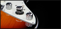 This also applies to the main model selector switch and consequently is the cause for many problem luthiers face building these project guitars. The main model selector switch in reality is NOT a switch, but a pot, potentiometer, just like the volume and tone controls. Fastened to its shaft is a metal washer with a bump on it that presses against the inside surface of the model selector knob to give it the feel or click of a rotary switch. However once you disassemble this switch to remove it from the “donor” guitar and then re-assemble it on the project guitar, it is very likely that you have put the pot in a different position from where you started, causing different models to be on other than the ones the switch is selecting. To correct this you must put the Variax into the calibration mode and then rotate this “switch” to each extreme so that the micro processor can detect the exact voltage your pot is putting out at the “Custom I” and “Custom II” positions. It will then save that info and will always know depending on what voltage it is putting out, what model you have selected.
The Variax guitar has two different ways it outputs it’s actual audio. The first way is very simple, after the digital signal is processes by the model selector, volume, tone and pick-up selector the digital audio signal is the converted back to analog in the second half of of the CODEC, the D/A, Digital to Analog convertor. The converted analog signal is then amplified, buffered and fed to the 1/4″ output jack on the guitar so that you can plug this into your amplifier.
The other method is far more complicated but is the reason the Line 6 Variax is superior to all other systems out on the market today. The digital signal WHILE being processed by the model selector, volume, tone and pick-up selector is sent out a RJ45 jack on a Ethernet cable to Line 6 Variax input on one of their amps or floorboards. It remains in the digital mode until the final output of the amp or floorboard where it is converted to analog in their D/A, Digital to Analog convertor. Because your signal remains digital, the amp and guitar can act together as one unit. Changes made at guitar will be reflected directly into the amp and changes made at the amp will be reflected back into the guitar. For example if you had a patch on your amp for a Van Halen type sound the amp could tell the guitar to go to the “Spank” mode, with the pick-up selector in the “bridge” pick-up , the volume and tone wide open. You then switch the amp to a Acoustic setting and the guitar follows by switching to a jumbo acoustic with the mic positioned near the sound hole. All this switching occurs from just a simple push of a switch on either the amp or floorboard. Add alternate tunings to this elaborate setup and you can see the power you can have with just a simple foot switch.
The final part of the Variax system is the power. You have three ways you can power a Line 6 Variax guitar. First there are batteries. The Line 6 Variax requires 6 AA batteries for a total voltage of 9V but with a lot more current than a simple rectangular 9V battery can produce. These 6 Cell battery packs are not rechargeable in the guitar and require a lot of attention so that the batteries don’t die and then leak all over the guitar’s electronics. The second method is via a stereo TRS, Tip/Ring/Sleeve, 1/4″ cable. This plugged into a Line 6 inline power box can supply the 9V the guitar need to run. This method works fine and most people include the power box on their foot pedalboard. The last method is via the Ethernet cable. When you use the digital out of the guitar into a Line 6 amp or Effect board it will also supply the 9V the guitar needs. This is obviously the easiest method as their is no second though involved. Just plug the cable in and your on your way.
Our Project begins
In late 2008, I was contacted by the guitarist of a very well known local cover band here in Las Vegas. The band prides themselves being able to reproduce exact covers of well known bands songs. The guitarist needed a guitar that at one moment could produce the 12 string sound and tuning of Led Zepplin’s the Rain Song, and in the next moment go to the hard driving fuzz sound of Focus’s Hocus Pocus. He enlisted the aid of one of Las Vegas’s top luthiers’ to create a guitar based on a Ed Roman Custom Scorpion guitar. The guitar had a Floyd Rose Ghost Bridge with a Fernades Sustainer System and Variax 700 electronics.
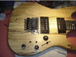 The luthier had done a beautiful job of routing, drilling, and modifying the body to fit all the electronics and controls into the guitar. Unlike some of these custom Variax projects where the output 1/4″ jack is fed via a toggle switch enabling you to select standard guitar or Variax guitar, this guitar had both sets of outputs on it so that the switching could be done at the Line 6 X3 Live floorboard where this guitar would plug in. That way with the dual tone and multiple selectable inputs on the X3 Live you can enable quite a few guitar/amp/tuning setups on the fly by just pushing a switch. A real powerhouse of tone capability with one problem though – it didn’t work. The guitar as presented to me had a variety of problems. First off the Line 6 Variax system was no longer calibrated and the modeling knob no longer corresponded to the models that were being heard. The 5 way switch did not switch the Line 6 models properly. The regular pick-ups were humming badly as soon as the Variax was plugged in and the Line 6 microprocessor clocks were being induced into regular guitar output so that in addition to the hum you heard a high pitched whine even with the main guitar volume turned down. The luthier had given up and the customer was left with a really nice looking “acoustic” guitar.
Prepping the cavity
Having seen the inside of enough Line 6 Variax guitars I knew it was essential to put the Line 6 electronics in a completely shielded box. This would keep all the artifacts that are produced from the various high speed microprocessor clocks used to keep the DSP running contained and not leaking into other electronics that are in close proximity of the Line 6 Main PCB. There are two ways to do this. The first one is very easy as you just paint the electronics cavity with a special shielded paint that is conductive. A couple coats of this paint provides a pretty effective shield from RF and should be adequate to contain the digital hash from leaving the electronics cavity. The second method, copper foil tape, while not as easy, I believe forms a better shield than the paint.
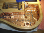 If you measure with an ohm meter you will find the copper tape has a lower resistance per foot value that the paint has.
The foil tape has a adhesive back to which you just stick it on the wood. You should prep the wood by making sure it is clean and free from dirt and dust so that the adhesive grips it securely. To provide an effective shield you slightly overlap edges leaving no exposed wood gaps. I then prefer to solder each seam so that the individual strips form one continuous piece.
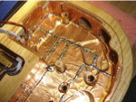 When you are done check it with an ohm meter to confirm you have a “one piece” shielded cavity with the same or lower resistance from any two places within the cavity. Another critical thing to do is to fold the tape over the top edge in more than one place on the cavity, especially where the screw holes are. That way when the plastic cover, which you also line with the shielded tape, closes over the cavity, the two meet and “electrically” connect together now forming a sealed completely shielded box. I don’t like to take the risk of melting the plastic cover so I don’t solder the seams on it. I figure if you overlap the edges on the cavity properly each strip on the cover will be touching the cavity on both ends so you still wind up a shielded box, except with a “vented” top, if you really can call it that.
Dividing the electronics
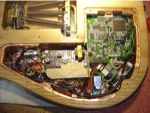 Another critical issue to observe inside this cavity is to divide the analog section from the digital section. This will keep the stray digital noise from getting into the analog parts, like the Fernades preamp board in this guitar. Since the Luthier had already mounted these components, I was forced to wedge a small piece of cardboard, with shielded tape on each side down between the two PCB’s. Of course I soldered this piece of cardboard to the main cavity where possible so that it formed a “electrical”” shield between the two. You will observe that I didn’t go all the way across in order to leave room for all the wires to pass from one section to another. Now you may be wondering what good this does if the Variax controls are over in the Analog section like they are in this guitar. But remember from our discussion above, the only thing you will find on those controls are DC voltages. No high speed clocks or digital lines. So they are very clean “electrically” and will not induce any noise into the analog signal.
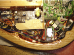 The other thing to observe is since the analog or main pick-ups output jack is located in the digital section the output wire from the main volume control to the jack MUST be completely shielded. I tried to keep the unshielded wire, where it is soldered to the jack, as short as possible in order to give this wire maximum shielding since it was located close to the Variax Main PCB. I even thought of forming a shield between the exposed jack contacts and the PCB but decided against it due to the fact it was too close to the PCB and the shield may wind up touching the jack shorting out the signal. If I was routing and drilling this cavity I would have moved that jack down enough that you could shield it from the Main PCB, since this could be a potential leak in your shielding system.
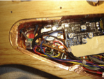 One more thing regarding this output jack is that it was mounted to a small square of plastic which was screwed to the side of the body of the guitar. Since the actual sleeve on this jack was soldered to the shielded wire going to the volume control, the jack would not “see” the actual shielded chassis ground until it hit the volume control way over on the left. This was remedied by a small wire from the jack shield to the copper shield close to the jack but still allowing the jack to be removed and replaced when necessary. You could have gone a step farther and shielded the small plastic square the jack was screwed to and also the hole routed into the wood with the shield overlapping so that once the plastic was screwed on it would make contact, but I thought the wire would provide the immediate chassis ground I was looking for without the additional fuss.
Wiring in the Piezos
Since Luthiers are in fact Luthiers and not Electronic Technicians, they all seem to hook up the Piezos the same way. They remove all the interface wiring from the donor guitar and then add it into their project guitar. This interface wiring was selected by Line 6 in order to wire it to their particular bodies and may or may not be needed in it’s entirety in your body. Basically the Piezos need to connect to the 6 places on the Line 6 Main PCB labeled A, B, C, D, E, and F, with A being the high e string. Do this as quickly and neat as possible without any additional wire. You should leave some sort of disconnect between the Main PCB and the Piezos in case a Piezo goes bad or in case you have to replace the entire Main PCB. This particular guitar had the new ghost bridge Piezos wired to a 12 pin connector which then wired to the Line 6 bridge PCB. The Bridge PCB then connected to a flexi ribbon cable which then plugged into the Main PCB. Not being a fan of the flexi ribbon cable, I removed the flexi ribbon connector from the Main PCB and soldered the already terminated 12 pin connector wire directly to the Line 6 PCB. Granted if you need to change out the Main PCB you will have to unsolder and re-solder those 7 wires (6 strings plus a ground) to the new one, but you have eliminated at least 10 inches of wire and 28 connections just waiting to cause problems.
Conclusion
Within a few days this special guitar went from “unusable” to being used regularly on stage 4 to 5 nights a week. While these type of guitars are beyond the capabilities of most Luthiers they are not beyond what we are capable of doing at Thermal Relief Design, Inc.
Give us a call to see if we can make your vision come true