How to properly disassemble a Focusrite Red Series unit

Using a 6 mm hex wrench, you must loosen and then completely remove the (2) 6 mm screws on the Right Front Side.
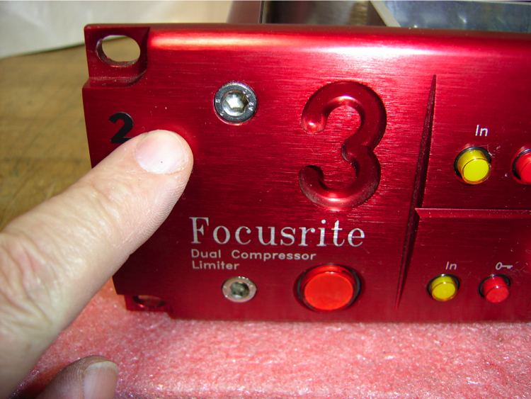
On the Left Front Side, loosen the (2) 6 mm screws a couple of turns but DO NOT REMOVE THEM.
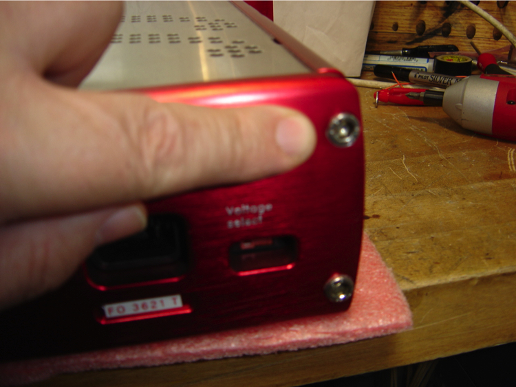
Turn the unit around and on the Right Rear Side also loosen but DO NOT REMOVE the (2) 6 mm screws.
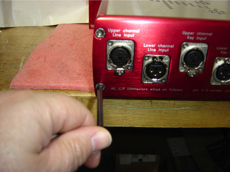
Now on the Left Rear Side, loosen and completely remove the (2) 6 mm screws.
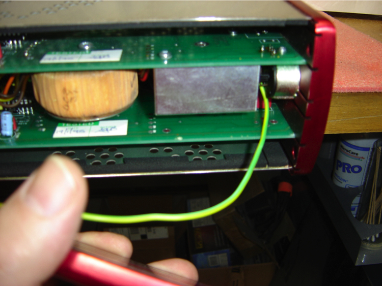
Now you can carefully remove the right side panel. There will be a ground wire that goes from the panel to the bottom PCB board. The easiest way to disconnect the panel is to pull the “sta-con” connector from the PCB. Although on some RED units like the early RED 3 pictured above the connector is kinda buried. In this case you could just unscrew the other end from the side panel.
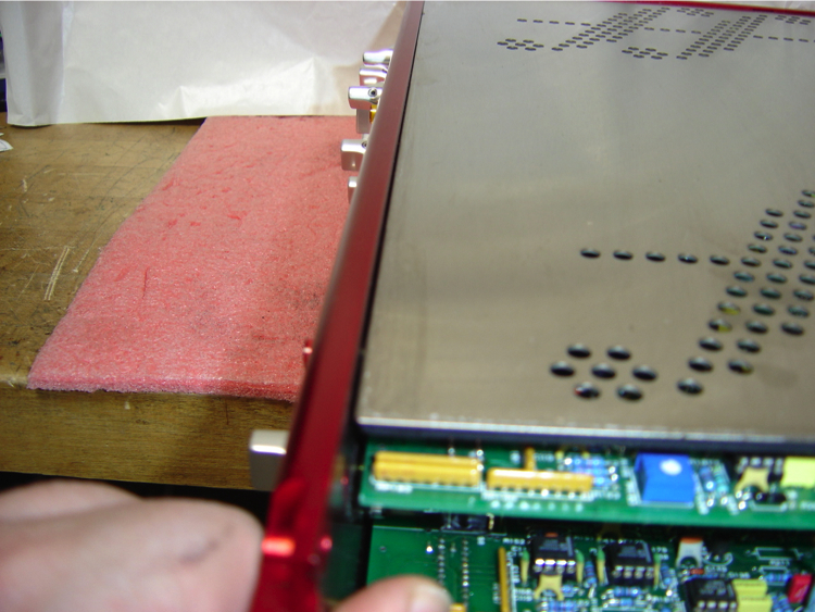
Carefully pry the front and back panels apart at the open end just enough to reveal a slight opening between the top cover and the front and rear panels like shown in the picture above.

Now grasp the stainless steel top cover and pull it towards you.
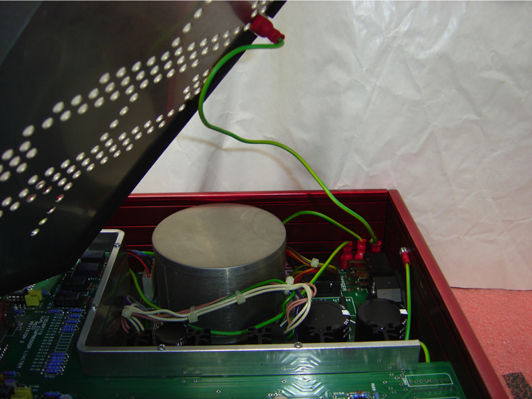
You will not have to slide it all the way out as it will come loose because you have already made one end wider in the previous steps. So to fully remove the cover, grasp Green ground wire near the “sta-con” and pull it loose from the PCB.
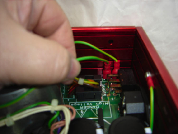
Also pull out the other Green wire that goes in front of the Mains Transformer. This is connected to the stainless steel bottom cover. Leave the one that is wedged between the Transformer and the left side panel connected.
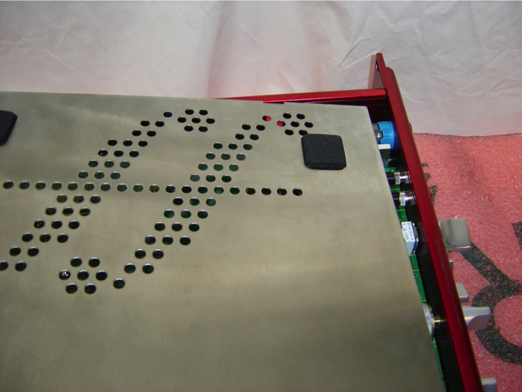
Turn the unit over and carefully remove the bottom cover just like you did the top cover in the previous steps.