Gain Reduction or Compression Meter
Calibrating a compressor/limiter is a task best left to a technician with the proper test equipment however calibrating the Gain Reduction Meter is something most people could do themselves once you have a proper understanding what it’s actually reading and how to measure/adjust it. The average single channel compressor normally has one VU meter and some type of switch that will allow that single meter to do three different functions; Input, Output, and Gain Reduction. Let’s take a look at each function and how to calibrate them.
INPUT
Obviously before proceeding you should have set your VU meter mechanical rest position first as I have explained in the Mechanical Rest Tech Tip TWTA001. The Input Meter function is fairly simple and straight forward. First switch the meter function switch to Input and then inject a 1kHz sine wave at +4 dBu (1.228 Volts) into the input of your compressor. Be sure to measure the output of your sine wave generator to insure that it is outputting exactly +4 dBu. Don’t worry about it being exactly 1kHz as that is not as important as it being exactly +4 dBu in amplitude. So with +4 dBu going into the compressor you just turn the internal input meter trim pot until the meter of the compressor reads 0 VU. (see below) That was simple right? Please note not all compressors have a Input Meter function and/or a trim adjustment for it.
OUTPUT
Again this is pretty straight forward like the Input Meter above with one exception – you must make sure the compressor is not compressing at all. The best way is to put the Threshold control all the way up, (+20 as opposed to say -20) and/or the Ratio Control at 1:1. You could use the bypass switch however many times the bypass function will be a “hardwire” bypass which will take the input signal and send it directly to the output bypassing all the electronics on the unit, including the trim pots you are trying to adjust. Also before adjusting the output meter, be sure that the Make-up gain control is turned all the way down so that you are not adding any additional gain to the output. Now switch the Meter Function to Output and adjust the internal output meter trim pot until the meter of the compressor reads 0 VU just like you did above. (Obviously you should still be injecting a 1kHz sine wave at +4 dBu into the input of the compressor.) After calibrating the Output function you should now be able to switch the meter between Input and Output and the needle should remain at 0 VU for both positions. OK the easy part is over.
GAIN REDUCTION
To make it easier to calibrate the Gain Reduction Function you should first understand what the GR meter is actually doing. Since the compressor is actually reducing the gain (compressing the signal) then the GR meter has to show that. So in the GR Function the meter will actually “rest” at 0 VU instead of the mechanical rest position. Then when the compressor reduces (compresses) the signal the meter will go downwards towards the -20 position instead of going up like a conventional meter. So obviously to read the meter, wherever the needle points to below 0 VU is the amount of gain reduction the compressor is compressing. Then to calibrate it all we need to do is make the compressor reduce the signal by a set amount and set the meter to read that. That’s fairly simple right?
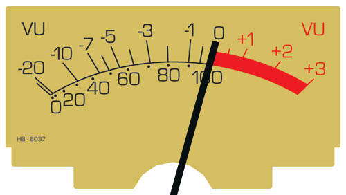
OK the first step is to switch the meter into the Gain Reduction mode. With no signal going into the unit you set the GR zero trim pot (this may be called lots of different things) so that the meter reads exactly 0 VU. (see below)
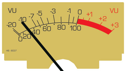
Now with the Threshold all the way up and the Ratio at 1:1 you inject a 1kHz sine wave at +4 dBu into the input of your compressor. (A quick check of the meter function switch should revel the meter will be at 0 VU for ALL three functions; Input, Output, and Gain Reduction.) Then turn the ratio up to say 5:1 (2:1, 3:1, 5:1 not really important which ratio unless you were calibrating the compressor, the important thing is that it compresses) and turn the Threshold down until you read exactly -6 dBu on a EXTERNAL meter connected to the output of the unit. Let’s think for a minute… You started with +4 dBu and now you have -6 dBu so you have reduced or compressed the signal by exactly 10 dB. So now you just adjust the internal -10 Meter trim pot (once again this may be called lots of different things) so that the needle points to exactly -10 VU. (see below)
Ahh, but we are not done. This will cause the 0 VU gain Reduction position to move so we must go back to the last step, remove the signal, and re-adjust the GR zero trim pot again so the needle is exactly back on 0 VU. Then re-apply the signal and adjust for -10 again, etc., etc., etc. So basically you keep going back and forth between these two steps until the needle reads exactly -10 VU when -6 dBu is coming out and 0 VU when nothing is coming out.
LET”S CHECK IT ALL OUT…
Now if you have done everything correctly with the same settings for Threshold and Ratio as above, you should be able to inject a 1kHz sine wave at +4 dBu into the input of your compressor, measure -6 dBu on a external meter connected to the output and see the following VU meter pictures when you switch the between the 3 different functions. (see below)
INPUT
OUTPUT
GAIN REDUCTION
That’s it, your Gain Reduction Meter is now calibrated. So go make some music!